
Having bought a good laptop or a cool phone, we rejoice in the purchase, admiring the set of features and speed of the device. But it is necessary to connect the gadget to the speakers to listen to music or watch a movie, we understand that the sound produced by the device, as they say "drove". Instead of full and clean sound, we hear a neuroent whisper with background noise.

But do not be upset and scold manufacturers, the problem with sound can be solved on your own. If you understand the chips and know how to solder well, you will not be difficult to make your own amplifier sound. In our article, we will tell how to make a sound amplifier for each type of device.
How to make a sound amplifier?
At the initial stage of work on creating an amplifier, you need to find tools and buy component parts. The amplifier circuit is manufactured on a printed circuit board with a soldering iron. To create chips, use special soldering stations that can be bought in the store. Using a printed circuit board allows you to make a device compact and easy to operate.
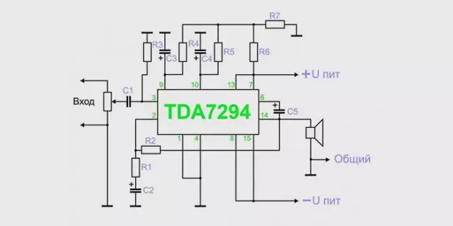
Amplifier sound frequency
Do not forget about the features of compact single-channel amplifiers based on the chip of the TDA series, the main of which is the allocation of a large amount of heat. Therefore, try with an internal amplifier device, exclude microcircuit contact with other parts. For additional cooling of the amplifier, it is recommended to use a radiator lattice for heat removal. The grid size depends on the model of the chip and the power of the amplifier. Place the place for the heat sink in advance in the amplifier housing.
Another feature of the independent manufacture of the sound amplifier is low energy consumption. This in turn allows you to use the amplifier in the car by connecting it to the battery or on the road using the battery power. Simplified amplifier models require a voltage of the current only in 3 volts.
The main elements of the amplifier
If you are a starting radio amateur, then for more convenient work, we recommend that you use a special computer program - Sprint Layout. With this program you can create and view schemas on your computer. Note that the creation of your own scheme makes sense, only in that cases if you have sufficient experience and knowledge. If you are an inexperienced radio amateur, then use ready-made and proven schemes.
Below we will give the scheme and descriptions of different options for sound amplifier:
Headphone Sound Amplifier
Sound amplifier for portable headphones has no high power, but consumes very little energy. This is an important factor for mobile amplifiers that feed from batteries. Also on the device can be placed connector, to power from the network through the 3 volt adapter.
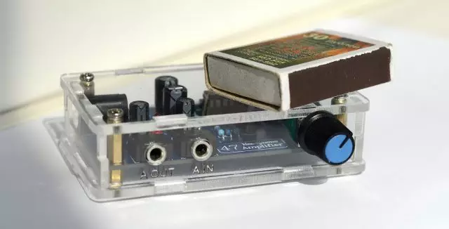
Homemade Headphone Amplifier
For the manufacture of an amplifier for headphones, you will need:
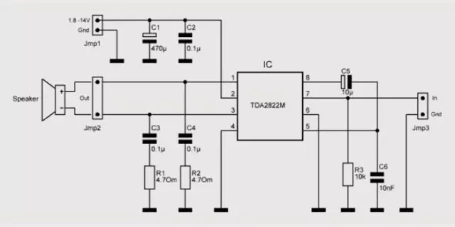
- Chip TDA2822 or analog KA2209.
- Amplifier assembly scheme.
- Capacitors 100 μF 4 pieces.
- Nest for headphone plug.
- Connector for the adapter.
- Approximately 30 centimeters of copper wire.
- Heat sink element (for a closed case).
Headphone Amplifier Scheme
The amplifier is made on the printed circuit board or mounted installation. Do not use the pulse transformer in this form, since it can be interfered. After making, this amplifier is able to provide a powerful and pleasant sound from the phone, player Go Tablet.
More than one option of the homemade amplifier for headphones, you can get acquainted in the video:
Laptop audio amplifier
The laptop amplifier is going in cases where the power of the dynamics built into it is not enough for normal listening, or if the speakers failed. The amplifier must be designed for external speakers up to 2 watts and winding resistance up to 4 ohms.
Article on the topic: How and how to paint a veneered door

Laptop audio amplifier
To build an amplifier, you will need:
- Printed circuit board.
- TDA 7231 microcircuit.
- 9 volt power supply.
- Case for placement of components.
- Condenser non-polar 0.1 μF - 2 pieces.
- Condenser Polar 100 μF - 1 piece.
- Condenser Polar 220 μF - 1 piece.
- Condenser Polar 470 μF - 1 piece.
- Resistor permanent 10 com - 1 piece.
- Resistor constant 4.7 ohms - 1 piece.
- Switch two-position - 1 piece.
- The nest for entering the loudspeaker is 1 piece.
Laptop audio amplifier circuit
The order of assembly is determined independently depending on the scheme. The cooling radiator must be of such a size so that the operating temperature inside the amplifier housing does not exceed 50 degrees Celsius. If you plan to use the device outdoors, it is necessary to make a housing with holes for air circulation. For the housing, you can use a plastic container or plastic boxes from under the old radio equipment.
You can view visual instructions in the video:
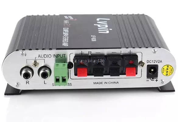
Sound amplifier for car radio
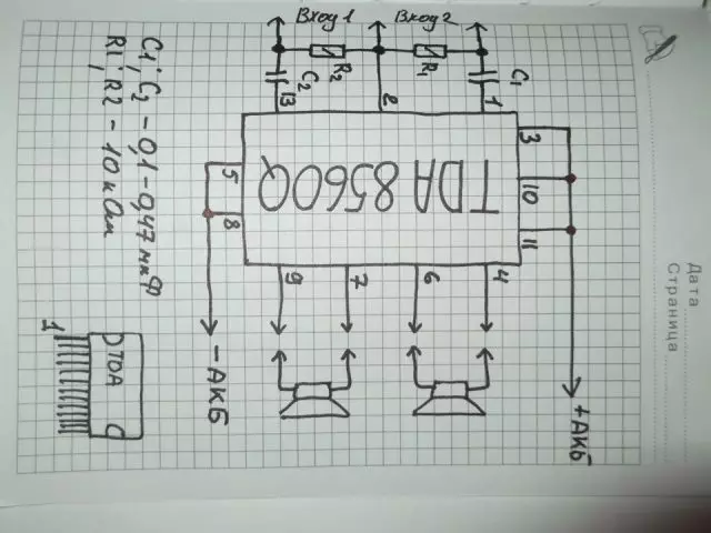
This amplifier for the car radio is assembled on the TDA8569Q chip, the scheme is not complicated and very common.
Sound amplifier for car radio
The microcircuit has the following stated characteristics:
- Input power 25 watts per channel in 4 ohms and 40 watts per channel in 2 ohms.
- Power supply 6-18 volts.
- Range of reproducible frequencies of 20-20000 Hz.
For use in the car, the diagram must add a filter from interference that are created by the generator and the ignition system. The microcircuit also has a short-circuit protection and overheating.
Sound Amplifier Scheme for AvtoGNITOL
Checking with the presented scheme to purchase the necessary components. Next, draw a printed circuit board and drill holes in it. After that, spend the board with chlorine iron. In conclusion, Ludim and begin to solder microcircuit components. Note that the pathways of the power is better to cover the thicker layer of the solder so that there are no evidence for food.
On the chip need to install the radiator or organize active cooling with the help of a kuller, otherwise, with an increased volume, the amplifier will overheat.
After assembling the chip, you need to make a power filter according to the following scheme:
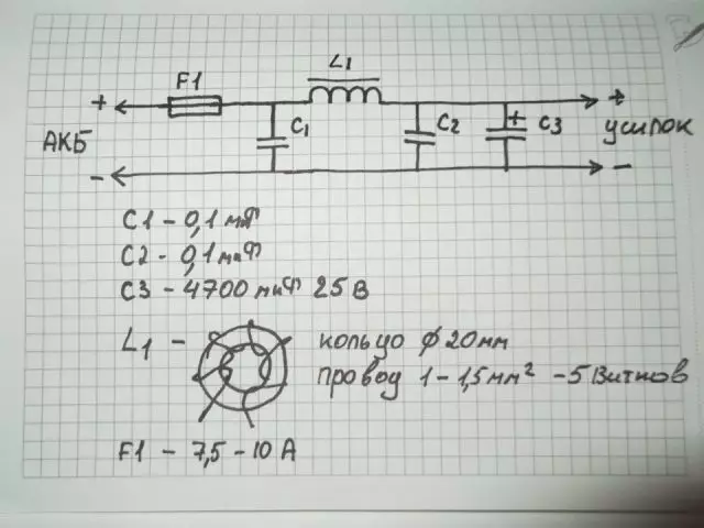
Filter Filter Scheme
The throttle in the filter dulls in 5 turns, with a wire with a cross section of 1-1.5 mm, on the faith ring with a diameter of 20 mm.
Also, this filter can be used if your tape recorder catches "pressing".
Attention! Be careful and do not confuse the polarity of the power, otherwise the microcircuit is combined instantly.
How to make an amplifier for stereo signal, you can also learn from the video:
Sound amplifier on transistors
As a circuit for a transistor amplifier, use the scheme below:
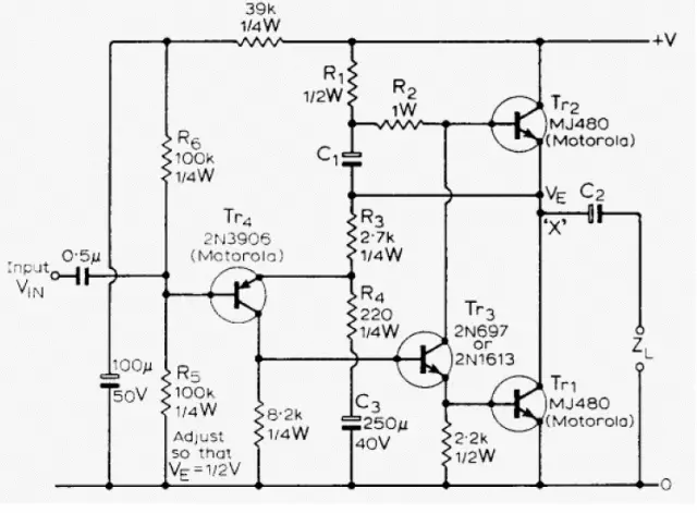
Sound transistor audio amplifier
The scheme, though old, but has a lot of fans, for the following reasons:
- Simplified installation due to the small number of elements.
- There is no need to sort out transistors into complementary pairs.
- 10 watt power, with a margin enough for residential rooms.
- Good compatibility with new sound cards and players.
- Excellent sound quality.
Start assembling a power amplifier. Divide the two channels for stereo with two secondary windings running from one transformer. On the layout, make bridges on Schottky diodes for rectifier. After the bridges are CRC filters from two capacitors of 33,000 Igf and between them a resistor 0.75 ohms. The filter resistor needs a powerful cement, with a sheek current to 2a, it will dispel 3 W heat, so it is better to take with a reserve of 5-10 W. The rest of the resistors in the scheme, the power of 2 W will be enough.
Article on the topic: how to paint the iron gate beautiful and for a long time
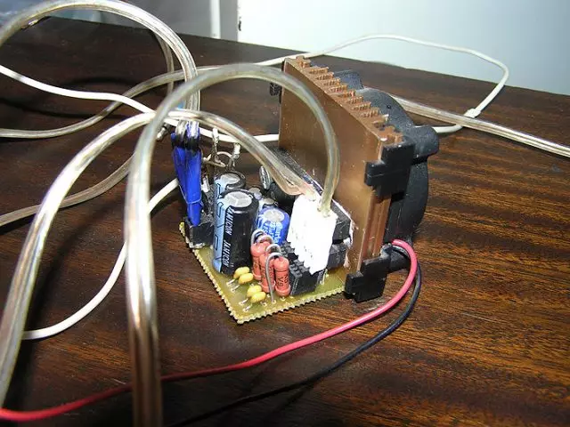
Amplifier on transistors
Go to the boost of the amplifier. All except the weekend transistors TR1 / TR2 is located on the board itself. Output transistors are mounted on radiators. Resistors R1, R2 and R6 are better to first put rapidly, after all adjustments to fall, measure their resistance and solder final constant resistors with similar resistance. The setting is reduced to the following operations - with R6 is set to the voltage between X and zero to be exactly half of the voltage + v and zero. Then, with the help of R1 and R2, the rest current is set - we put the Tester to measure direct current and measure the current at the Power Power Input point. The rest of the amplifier in the class A maximum and in fact, in the absence of an input signal, everything goes into thermal energy. For the 8-ohmic columns, this current must be 1.2 and at a voltage of 27 volts, which means 32.4 Watt heat per channel. Since the current setup may take a few minutes, the weekend transistors must already be on cooling radiators, otherwise they will quickly overheat.
When adjusting and understating the resistance of the amplifier, the frequency of the CBC can grow, so it is better to use 5.5 μF for the inlet capacitor, and 1 or even 2 μF in the polymer film. It is believed that this scheme is not prone to self-excitation, but just in case there is a chain of Tsobel between the point X and the earth: R 10 Ohm + with 0.1 μF. Fuses need to be placed both on the transformer and on the power input of the circuit.
A good idea will be the use of the thermal paste for maximum contact between the transistor and the radiator.
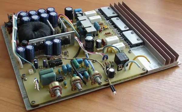
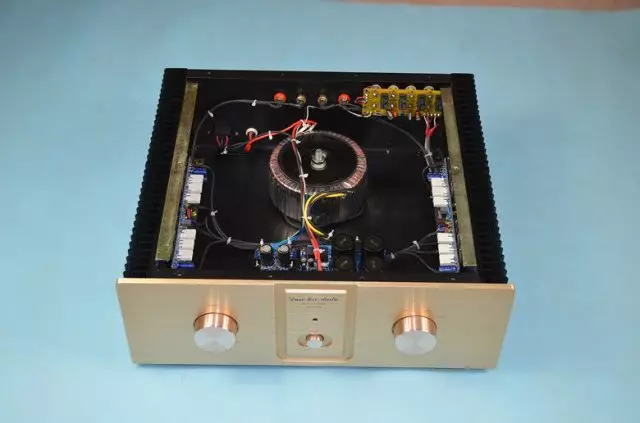
Now a few words about the case. The size of the housing is set by radiators - NS135-250 at 2500 square centimeters per transistor. The hull itself is made of plexiglas or plastics. Collect the amplifier before starting to enjoy the music, it is necessary to minimize the background to properly divorce the land. To do this, attach the SZ to the minus of the login, and output the remaining minus to the "star" near the filter condensers.
Sound amplifier case on transistors
Exemplary cost of consumables for transistor audio amplifier:
- Filter condensers 4 pieces - 2700 rubles.
- Transformer - 2200 rubles.
- Radiators - 1800 rubles.
- Weekend transistors - 6-8 pieces of 900 rubles.
- Small elements (resistors, condensers, transistors, diodes) around - 2000 rubles.
- Connectors - 600 rubles.
- Plexiglas - 650 rubles.
- Paint - 250 rubles.
- Board, wires, solder about - 1000 rubles
As a result, the amount is 12,100 rubles.
You can also watch a video amplifier assembly video on Germany transistors:
Lamp sound amplifier
A simple lamp amplifier circuit consists of two cascades - a pre-amplifier at 6N23P and power amplifier at 6P14P.
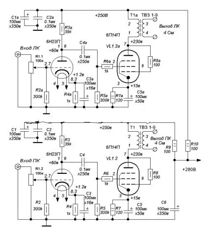
Lamp amplifier circuit
As can be seen from the scheme, both cascades work in a triotode inclusion, and the anode current of the lamps is close to the limit. Currents are built up with cathode resistors - 3ma for the input and 50mA for the output lamp.
Details used for the lamp amplifier must be new and high quality. The permissible deviation of the resistor denominations may be plus-minus 20%, and the capacity of all capacitors can be increased by 2-3 times.
Filter capacitors must be calculated on voltage at least 350 volts. An intercountable capacitor should be calculated for the same tension. Transformers for the amplifier can be ordinary - TV31-9 or more modern analog - TWSE-6.
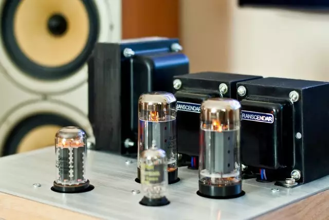
Lamp sound amplifier
The volume and stereo balance controller to the amplifier is better not to install, since the adjustment data can be made in the computer or player. The entrance lamp is selected from - 6N1P, 6N2P, 6N23P, 6H3P. 6P14P, 6P15P, 6P18P or 6P43P (with increased resistance of the cathode resistor) are used as the output penter.
Even if you have a working transformer, it is better to use a conventional transformer with a 40-60 watt rectifier for the first turning on the paw amplifier. Only after successful testing and adjustment of the amplifier can be installed a pulse transformer.
Use the standard for plugs and cables to connect the speakers to install "pedalings" to 4 contacts.
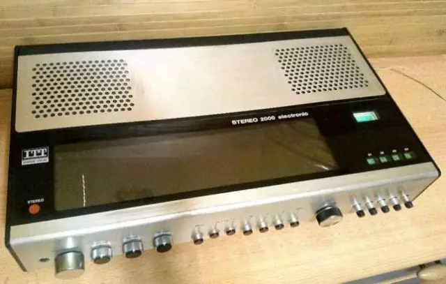
The housing for the paw amplifier is usually made from the shell of old equipment or casing system blocks.
Another option of the lamp amplifier you can see the video:
Article on the topic: Drying the vinyl wallpaper after sticking
Classification of sound amplifiers
So that you can determine which class of sound amplifiers belongs to the device you collected, check out the classification of UMPs below:
- Class A. - The amplifiers of this class work without cut-off at the linear portion of the voltamper characteristics of the amplifying elements, which ensures minimum of nonlinear distortion. But for this you have to pay a large amplifier size and a huge power consumed. The CPD of the class A amplifier is only 15-30%. This class includes lamp and transistor amplifiers.
- Class B. - Class amplifiers in work with a cut-off signal of 90 degrees. For this operation mode, a two-stroke scheme is used, each part enhances its half of the signal. The main minus class B amplifiers is the distortion of the signal due to the step transition of one half-wave to the other. The plus of this class of amplifiers consider the high efficiency, sometimes reaching 70%. But despite the high performance, modern models of the class B amplifier, you will not meet on the shelves.
- Class AU. - This is an attempt to combine the amplifiers described above, in order to achieve the lack of signal distortions and a high efficiency.
- Class N. - Developed specifically for cars, which have a voltage limit that feeds output cascades. The reason for the creation of class H amplifiers is that the real beep has a pulse character and its average power is much lower than peak. The scheme of this class of amplifiers is based on a simple scheme for AB class amplifier operating on a bridge circuit. Only a special supply voltage doubling scheme has been added. The main element of the doubling scheme is a cumulative capacitor of a large capacity, which is constantly charging from the main power source. At power peaks, this capacitor connects the control circuit with the main power source. The supply voltage of the output stage of the amplifier doubles, allowing it to cope with the transmission of the signal peaks. The efficiency of class H amplifiers reaches 80%, while distorting the signal is only 0.1%.
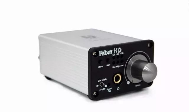
- Class D is a separate class of amplifiers called - "Digital amplifiers". Digital conversion provides additional sound processing options: from adjusting the volume and timbre to the implementation of digital effects, such as reverb, noise suppression, acoustic feedback. Unlike analog amplifiers, the output signal of the class D amplifiers is a rectangular pulse. Their amplitude is constant, and the duration varies depending on the amplitude of the analog signal entering the input of the amplifier. The efficiency of this type of amplifiers can reach 90% -95%.
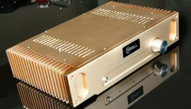
Amplifier class A.
Class B Amplifier
AV. A amplifier
Amplifier class N.
Amplifier class D.
In conclusion I would like to say that the activity of electronics requires a large amount of knowledge and experience that are purchased for a long time. Therefore, if something has not happened, do not be discouraged, reinforce your knowledge from other sources and try again!