
With an increase in electricity prices, it is necessary to think about more economical luminaires. Some of these use daylight lighting devices. The diagram of connecting fluorescent lamps is not too complicated, so even without special knowledge of electrical engineering can be sorted out.
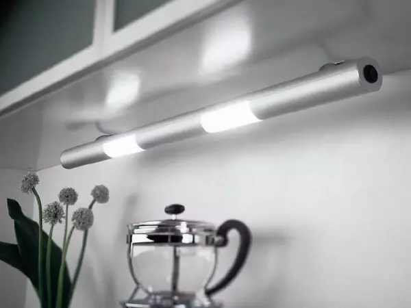
Good illumination and linear dimensions - the benefits of daylight
The principle of the fluorescent lamp
In daylight lamps, the ability of mercury vapor emit infrared waves under the influence of electricity. In the video visible for our eyes, this radiation translates the phonophores.
Therefore, the usual fluorescent lamp is a glass flask, the walls of which are covered with a luminophore. Inside there is also some mercury. There are two tungsten electrodes that provide emissions of electrons and heating (evaporation) of mercury. The flask is filled with inert gas, most often - argon. The glow begins in the presence of mercury steams, preheated to a certain temperature.
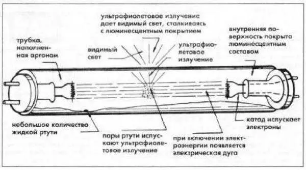
Fundamental Luminescent Daylight Lamp
But for the evaporation of mercury of the usual voltage of the network is not enough. To start work, parallel with the electrodes include commissioning devices (abbreviated PRA). Their task is to create a short-term voltage jump required to start the glow, and then limit the operating current without allowing its uncontrollable increase. These devices are pra - there are two types - electromagnetic and electronic. Accordingly, the schemes differ.
Schemes with starter
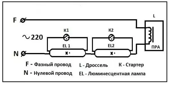
Schemes with starters and throttle appeared. These were (in some embodiments) two separate devices, each of which had its own socket. Also in the scheme there are two capacitors: one is turned on in parallel (to stabilize the voltage), the second is in the starter housing (increases the duration of the starting pulse). It is called all this "economy" - electromagnetic ballast. The diagram of the luminescent lamp with the starter and choke - in the photo below.
Article on the topic: Decorative stone in the hallway - styling secrets
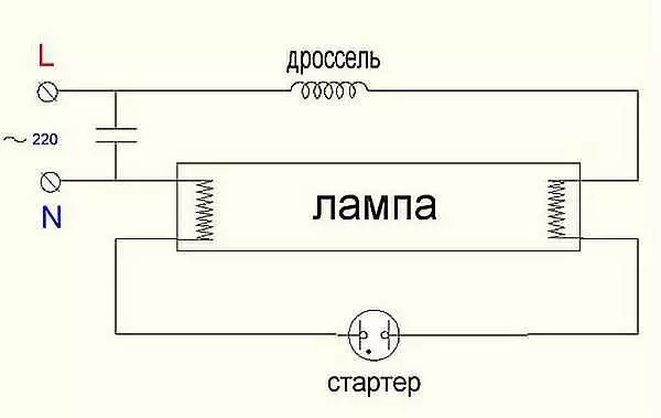
Connection diagram of fluorescent lamps with starter
Here's how it works:
- When power is turned on, the current flows through the throttle, falls on the first tungsten spiral. Next, through the starter gets into the second helix and goes through a zero conductor. At the same time, tungsten threads are gradually rolled as the starter contacts.
- The starter consists of two contacts. One fixed, second moving bimetallic. Normally, they open. When current passes, bimetallic contact is heated, which leads to the fact that it bends. Bending it, it connects with a fixed contact.
- As soon as the contacts were connected, the current in the chain instantly grows (2-3 times). It limits only choke.
- Due to the sharp jump, the electrodes are very quickly warmed up.
- Bimetallic starter plate cools and breaks contact.
- At the time of the contact breaks, there is a sharp voltage jump on the throttle (self-induction). This voltage is enough to ensure that the electrons break through the argon medium. Rajigue occurs and gradually the lamp goes to the operating mode. He comes after all mercury evaporated.
The operating voltage in the lamp is below the network to which the starter is designed. Therefore, after the ignition, it does not work. In the operating lamp, its contacts are open and he does not participate in her work.
This scheme is also called an electromagnetic ballast (EMB), and the operation scheme is an electromagnetic port-adjusting device - Empra. Often this device is called just choke.
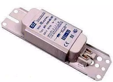
One of Empra
The disadvantages of this luminescent lamp connection scheme is enough:
- pulsating light that negatively affects eyes and they quickly get tired;
- noises when starting and work;
- the impossibility of running at low temperatures;
- Long start - from the moment of inclusion takes about 1-3 seconds.
Two tubes and two chokes
In the lamps on two daylight lamps, two sets are connected sequentially:
- phase wire is fed to the choke input;
- From the output of the throttle goes to one contact lamp 1, from the second contact goes to starter 1;
- From starter 1 goes to the second couple of contacts of the same lamp 1, and free contact is connected to a zero power wire (N);
Article on the topic: Mosquito net from cable channels with their own hands (20 photos)
The second tube is also connected: first the throttle, from it - one contact lamp 2, the second contact of the same group goes to the second starter, the starter output is connected to the second pair of contacts of the lighting device 2 and the free contact is connected to the zero input wire.
Connection diagram for two daylight lamps
The same diagram of connecting a two-color lamp of daylight is demonstrated in the video. It may be easier to deal with wires.
Connection diagram of two lamps from one choke (with two starters)
Almost the most expensive in this scheme - choke. You can save, and make a double-block lamp with one choke. How - look in the video.Electronic ballast
All the shortcomings of the scheme described above stimulated the survey. As a result, the electronic ballast scheme was developed. It that serves not a network frequency of 50Hz, but high-frequency oscillations (20-60 kHz), thereby removing the blinking of light very unpleasant eye.
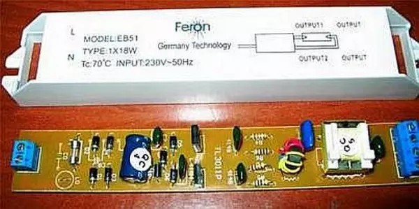
One of the electronic ballasts - EPR
The electronic ballast looks like a small block with derived terminals. Inside there is one printed circuit board, on which the whole scheme is collected. The block has small dimensions and mounted in the case of even the smallest luminaire. The parameters are selected so that the start occurs quickly, silently. No more devices need to work. This is the so-called unpleasant inclusion scheme.
On each device on the reverse side scheme is applied. It immediately clear how many lamps connect to it. Information is duplicated in inscriptions. The power of the lamps and their number, as well as the technical characteristics of the device, are indicated. For example, a block in the photo above can only serve only one lamp. The circuit of its connection is on the right. As you can see, nothing is complicated. We take the wires, connect the conductors with the specified contacts:
- First and second block output contacts connect to one pair of lamp contacts:
- The third and fourth are fed to another pair;
- To the entrance is supplied.
Article on the topic: Children's table DIY: Materials, Tools
Everything. Lamp works. Not much more complicated for the inclusion scheme of two fluorescent lamps to EPR (see the diagram in the photo below).
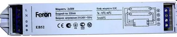
EPR for two daylight lamps
The advantages of electronic ballasplings are described in the video.
The same device is mounted in the base of daylight lamps with standard cartridges that are also called "economylampames". This is a similar lighting device, only strongly modified.
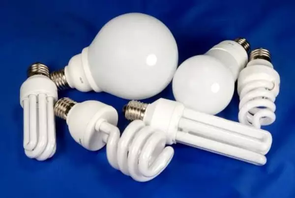
These are also fluorescent lamps, only the form is different