On this page of the site you will find
Instructions, how to install a suspended ceiling
Armstrong. To describe the mounting of the suspended ceiling Armstrong
We included such subsections as:
Profiles used for mounting
Suspended ceiling Armstrong;
Scheme
Installation of the suspended ceiling Armstrong and some elements
designs;
Material consumption
installation of suspended ceiling using 3 standard installation schemes;
Installation recommendations.
Procedure for mounting the suspended ceiling Armstrong
The suspension system is designed for distributed load - 3.5 ...6.0 kg / m 2 on the weight of the ceiling panels, and also imposed on top
(if necessary) layer of insulation materials. Bearing profiles
Frame (T24H38; T15x38, Table No. 1) on adjustable spring suspensions are attached
To the base is no more than 1,200 mm (Table No. 2). To prevent overload
the perimeter profile of the extreme suspension must be defeated from the walls
more than 600 mm with the weight of the ceiling products up to 4.0 kg / m 2 and 450
MM with weight more than 4.0 kg / m 2. Minimum frame distance from
The base should be at least 120 mm from the condition of the possibility
dismantling plates during operation.
In general, the installation of the suspended ceiling Armstrong is performed in the following order:
- measuring the room and breakdown the main mutually perpendicular axes;
- removal of pure ceiling marks on the walls and columns;
- ceiling markup from the axis of the room in both sides to identify
sizes of extreme to walls plates, locations of lamps, venerable and other devices;
- fastening the corner profile (PU profile 19/24) on the walls and columns using a dowel,
installed in 0.5 m;
- fastening of suspensions with rods to the base ceiling by means of anchor elements;
- installation of basic T-profiles 24x38 and aligning them in the same plane;
- installation of transverse T-profile 24x32 in the space of the main profile;
- installation of the longitudinal T-profile 24x28 in the crossbill of the transverse profile;
- Laying plates in the frame cells is made during the installation process of the frame or after it is completed. Laying to execute B.
The direction indicated by the arrows on the reverse side of the plates. Slabs
adjacent to walls, columns and other designs, trim around the place;
- if necessary, in the process of mounting the plates, laying the heat or sound insulation material;
- installation of lamps, ventilation grids, etc. Performed in the installation process.
Some requirements for mounting a suspended ceiling
Armstrong
Installation plates
produce only after the end of all construction and installation works,
including all the "wet" processes, as well as the device of floors and
glazing windows. The heating system should work to
The room could be ensured the temperature in the range of 15 - 30 ° C.
Relative humidity of the air should not exceed 70%.
Installing massive lamps, air conditioners, etc. should
exercised by hanging them on independent carriers
Designs.
In case of laying an additional layer of heat or
Soundproofing Material over Plates or Installation Installation
lamps should increase the number of suspensions in proportion
Increase the weight of the ceiling.
Table number 1. Profile T24 and T15 used to install a suspended ceiling
Bearing profile T15 and T24 |
|
|
Transverse Profile T15 and T24 |
|
|
Profile Corner 19/24. |
|
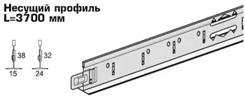
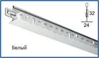
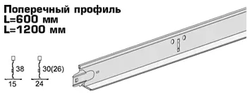
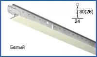
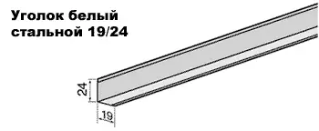
Table number 2. Armstrong suspended ceiling mounting diagram and some design elements
Armstrong suspended ceiling assembly scheme |
|
Fastening the profile suspension when mounting the suspended ceiling, the suspension length easily changes with the springs |
|
The docking of the profile to the wall occurs with the help of an angular profile 19/24 |
|
Transverse profiles have a castle at the ends, which when connecting transverse profiles with carriers Provides structural strength |
|
Transverse profiles insert from right from Friend in the slots of carrier profiles and lightweight effort up to Stop |
|
Beaching profiles have a reliable castle, Allows you to easily and quickly connect the flashes of two profiles. The shape of the slot provides quick and neat assembly |
|
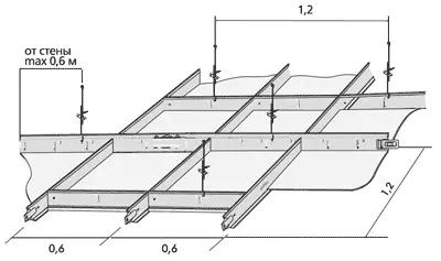
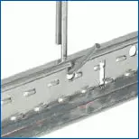
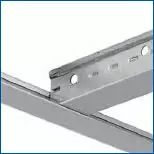
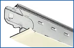
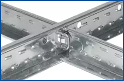
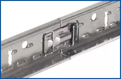
Table number 3. Material consumption when installing a suspended ceiling using 3 standard installation schemes
| Name of materials | units. change | Consumption per square meter | ||
|---|---|---|---|---|
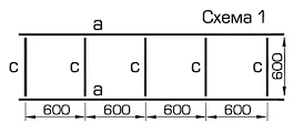
| Scheme 1.
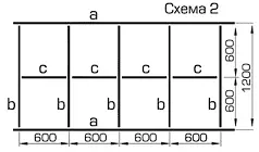
| Scheme 2.
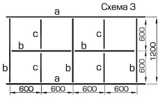
| Scheme 3.
| ||
| Brecking profile L = 3700 (a) | rm. M. | 1,68. | 0.84 | 0.84 |
| Transverse profile L = 1200 (b) | rm. M. | — | 1,68. | 1,68. |
| Transverse profile L = 600 (C) | rm. M. | 1,68. | 0.84. | 0.84. |
| Suspension S-3 | PC. | 2,4. | 1,2 | 1,2 |
| Dowel with semiring | PC. | 2,4. | 1,2 | 1,2 |
| White steel corner 19/24 | rm. M. | consumption depends on the perimeter of the room | ||
| Dowel for mounting a corner to the wall | PC. | At the rate of 2 dowel on 1 p. m perimeter | ||
| Ceiling plate | square meter | 1.0 |