
First of all, it is necessary to deal with what is a switching device and why it is required. Then to cope with the task of creating a MP-based scheme for lighting, heating, pumping pumps, compressors, or other electrical equipment will be much simpler.
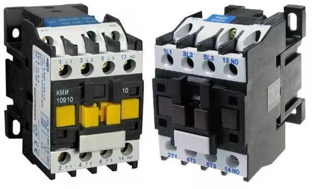
Contactors or so-called magnetic starters (MP) are electrical equipment designed to control and distribute the energy supplied to the electric motor. The presence of this device provides the following advantages:
- Protects from starting currents.
- In a well-compiled scheme, protection organs are provided in the form of electrical locks, chains of self-graffs, thermal relays, and the like.
- The control elements (buttons) are set to start the engine in reversal mode (reverse).
Contactor connection schemes are quite simple, allowing you to assemble the equipment yourself.
Purpose and device
Before connecting, you must familiarize yourself with the principle of the device and its features. Includes MP Controller Pulse, which comes from the launcher after pressing it. This is supplied to the voltage coil. According to the principle of self-blocking, the contactor is held in connection mode. The essence of this process is to parallel connecting the additional contact to the start button, which organizes the flow to the current coil, so the need to hold down the launch button disappears.With the equipment of the shutdown button in the circuit, it becomes possible to break the circuit of the control coil, which turns off the MP. Control button buttons are called a button post. They have 2 pairs of contacts. The universalization of the control elements is made to organize possible schemes with instant reverse.
Buttons are marked with the title and color. As a rule, including elements are called "Start", "Forward" or "Start". Designated green, white or other neutral color. For the blurring element, the name "Stop", the button of the aggressive, warning color, usually red.
The chain must be switched to the neutral, when using a 220 V coil in it for options with an electromagnetic coil with an operating voltage of 380 V, the control circuit is fed from another terminal. Supports work in a network with variable or constant voltage. The principle of the scheme is based on the electromagnetic induction of the used coil with auxiliary and work contacts.
Distinguish two types of MP with contacts:
- Normally closed - Turning off the power on the load occurs at the time of the starter.
- Normally open - power supply is carried out only during MP operation.
The second type is applied more widely, since most devices function a limited period, lasting the main time at rest.
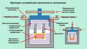
Composition and purpose of parts
The design of the magnetic contactor is the magnetic circuit and inductor coil. The magnetic core is the metal elements divided into 2 parts, the mirror to each other are located inside the coil. Their middle part plays the role of the core, enhancing the induction current.
Article on the topic: Reverers: installation with your own hands, features
The magnetic circuit is equipped with a movable top with fixed contacts to which the load is supplied. A fixed contacts are fixed on the MP housing on which the supply voltage is installed. Inside the coil on the central core, a rigid spring is installed, which prevents the connections to the contacts in the disabled state of the device. At the same time, the power supply is not served.
Depending on the design, there are MP small denominations of 110 V, 24 V or 12 V, but are more widely used with a voltage of 380 V and 220 V. The magnitude of the current current is distinguished by 8 categories of starters: "0" - 6.3 A; "1" - 10 A; "2" - 25 A; "3" - 40 A; "4" - 63 A; "5" - 100 A; "6" - 160 A; "7" - 250 A.
Principle of operation
In the normal (disconnected) state, the opening of the magnetic pipeline contacts provides installed inside the spring, lifting the upper part of the device. When connected to the MP network, an electric current appears in the chain, which, passing through the coils, generates a magnetic field. As a result of the attraction of metal parts of the spring cores, compression is subjected to compression, allowing the closure of the movement of the movable part. After that, the current gets access to the engine, running it to work.
Important: For AC or DC, which is supplied to the MP, it is necessary to withstand the nominal values specified by the manufacturer! Typically, for constantly current, the limit voltage value is 440 V, and for an alternating should not exceed the indicator 600 V.
If the "Stop" button is pressed or the MP power is turned off, the coil stops generating a magnetic field. As a result, the spring easily pushes the upper part of the magnetic pipeline, erosion contacts, which leads to the termination of the supply to the power load.
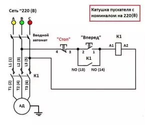
Connection diagram of a starter with a coil 220 V
To connect the MP, two separate chains are used - signal and working. The operation of the device is controlled by means of a signal circuit. The easiest way to consider them separately to make it easier to deal with the principle of organization of the scheme.Food on the device is supplied through the contacts of the MP contained on the upper part of the housing. They are denoted in schemes A1 and A2 (in standard execution). If the device is designed to work on a network with a voltage of 220 V, then it is that this voltage will be supplied to the specified contacts. There is no fundamental difference for connecting the "phase" and "zero", but usually the "phase" is connected to the A2, since this output is duplicated at the bottom of the housing, which facilitates the connection process.
To supply the load from the power source, contacts are used on the lower side of the case and marked as L1, L2 and L3. The type of current is not important, it may be permanent or variable, the main thing is to comply with the limit of the nominal limiting voltage of 220 V. to remove the voltage from the outputs with the designation T1, T2 and T3, which can be used to power the wind generator, battery and other devices.
The simplest scheme
When connecting to the contacts of the movable part of the MP network cord, with subsequent feed from the voltage battery, the value of 12 V, at the outputs L1 and L3, and to the outputs of the power circuit T1 and T3, to power the devices for lighting, the simple scheme is organized to light the room or space from Akb. This scheme is one of the possible examples of the use of MP in domestic needs.
Article on the topic: Telescopic Bathroom Rod: Pros and Cons
To feed the electric motor, magnetic starters are used much more often. To organize this process, apply voltage from the network 220 V at the outputs L1 and L3. The load is removed from the contacts T1 and T3 of the voltage of the same nominal.
These schemes are not equipped with a starting mechanism, i.e. When organizing buttons is not used. To stop the operation of the connected equipment through the MP, it is necessary to turn off the plug from the network. When organizing the circuit breaker in front of the magnetic starter, you can control the flow time without the need to complete disconnections from the network. Improve the scheme permissible pair of buttons: "Stop" and "Start".
Scheme with "Start" and "Stop" buttons
Adding control buttons to the scheme changes only a signal chain without affecting the power. The overall design of the scheme will suffer after such manipulations of minor changes. The control elements can be located in different housings or one. The single-block system is called a "push-button post". For each button, it is provided by a pair of outputs and inputs. Contacts on the "Stop" button - normally closed, on the "Start" - normally open. This allows you to organize the supply of power as a result of clicking on the second and turn the chain when initiating the second.Before MP, the data of the buttons are embedded sequentially. First of all, it is necessary to install "Start", which ensures the operation of the scheme only as a result of pressing the first control button until it is retention. When the switch is released, the power supply fails, which may not require the organization of an additional interrupt button.
The essence of the adjustment of the push-button post is the need to organize only pressing on the "Start" without the need for subsequent retention. To organize this, the coil shunt button is introduced, which is put on a self-pitch, organizing a chain of self-grade. The implementation of this algorithm is made by closing the MP auxiliary contacts. A separate button is used to connect them, and the inclusion time itself should be simultaneously with the "Start" button.
After clicking on the "Start" is passed through auxiliary power contacts, a closure chain. The need to hold the start button disappears, but it is required to stop pressing the corresponding STOP switch, which initiates the return of the circuit to normal.
Connecting to a three-phase network through the contactor with a 220 coil in
Three-phase food can be connected through a standard MP, which runs from a network with a voltage of 220 V. This scheme is permissible to use for switching in working with asynchronous motors. The control circuit does not change, the input contacts A1 and A2 serve "zero" or one of the phases. Through the "Stop" and "Start" buttons, a phase wire is skipped, and for the output normally open contacts jumper is equipped.
For the power circuit, certain minor amendments will be made. For three phases, the corresponding inputs L1, L2, L3 are used, where a three-phase load is derived from the outputs T1, T2, T3. To prevent overheating of the connected motor to the network, a thermal relay is embedded, which is triggered at a certain temperature, the erosion chain. This element is installed in front of the engine.
Article on the topic: Installation of ceiling panels on a wooden frame
Temperature control is performed on two phases, which differ in the greatest load. If the temperature on any of these phases reaches a critical value, an automatic shutdown is performed. It is often used in practice, noting high reliability.
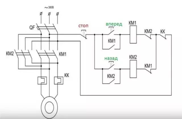
Engine connection circuit with reversed
Some devices work with engines that can rotate in both directions. If you transfer phases on the appropriate contacts, it is easy to achieve such an effect from any engine device. The organization of this can be done by adding to a push-button station except the "Start" and "Stop" buttons - "back".The MP scheme for reverse is organized on a pair of identical devices. It is better to choose a pair equipped with normally closed contacts. These parts are connected in parallel to each other, when organizing the back of the motor as a result of switching on one of the MPs, secure the phase in places. The load is fed to the outputs of both devices.
Organization of signal chains is more complicated. For both devices, the overall "stop" button is used, followed by the location of the Start control. The latter connection is made to the output of one of the MP, and the first to the output of the second. For each control, the shunting chain is organized for each control, which ensures the autonomous operation of the device after clicking on the "Start" without the need to retention. The organization of this principle is achieved through the installation on each MP jumpers on normally open contacts.
Electrical blocking is installed to prevent power supply to both control buttons. This is achieved by supplying the power after the "Start" or "forward" button to the contacts of another MP. Connecting the second contactor is similar, using its normally closed contacts in the first starter.
In the absence of normally closed contacts in the MP, by setting the console, you can add them to the device. With this installation, the operation of the contacts of the console is performed simultaneously with others by connection with the main unit. In other words, to break up normally closed contact after turning on the "Start" or "forward" button, which prevents the reverse move. To change the direction, the "Stop" button is pressed, and only after that another is "back". Any switching must be performed through the STOP button.
Conclusion
Magnetic starter is a very useful device for any electrician. First of all, it is easy to work with an asynchronous engine. When using the coil on 24 V or 12 V, feeding from the usual battery subject to the appropriate security measures, it turns out to even start the equipment designed for large currents, for example, with a load of 380 V.
To work with a magnetic starter, when drafting a circuit, it is important to take into account the features of the device and closely monitor the characteristics that are specified by the manufacturer. The outputs are strictly forbidden to supply a current of more voltage or strength than indicated in the marking.