
To supply power to engines or any other devices use contactors or magnetic starters. Devices intended for frequent power on and off. Connection diagram of a magnetic starter for a single-phase and three-phase network and will be considered further.
Contactors and starters - what's the difference
Both contactors and starters are designed for closing / opening contacts in electrical circuits, usually - power. Both devices are assembled on the basis of an electromagnet, it can be operated in the constant and alternating current circuits of different power - from 10 V to 440 V DC and up to 600 V alternating. Have:
- A number of working (power) contacts through which the voltage is supplied to the plug-in;
- A number of auxiliary contacts - to organize signal chains.
So what's the difference? What is the difference between contactors and starters. First of all, they are distinguished by the degree of protection. Contactors have powerful extinguishing chambers. From here there are two other differences: due to the presence of the dugheads, the contactors have a large size and weight, and also used in the circuits with large currents. For small currents - up to 10 A - release exceptionally starters. By the way, they are not produced on big currents.

The appearance does not always differ so much, but it happens
There is another constructive feature: the starters are produced in a plastic case, they only withdraw only contact pads. Contactors, in most cases, do not have the housings, therefore should be installed in protective housings or boxes that will protect against random touch to the current-carrying parts, as well as from rain and dust.
In addition, there is some difference in the appointment. Starters are designed to start asynchronous three-phase engines. Therefore, they have three pairs of strength contacts - to connect three phases, and one auxiliary, through which the power continues to be powered after the start button is released. But since such an algorithm of work is suitable for many devices, you connect through them a variety of lighting chains, various devices and instruments.
Apparently because the "filling" and the functions of both devices almost do not differ, in many prices, the starters are called "small-sized contactors".
Device and principle of operation
To better understand the magnetic starter connection scheme, it is necessary to figure it out in its device and the principle of operation.
The basis of the starter is a magnetic pipeline and a coil of inductance. The magnetic circuit consists of two parts - movable and fixed. They are made in the form of letters "sh" installed by "legs" to each other.
Article on the topic: Trelev in the interior: Vintage and modern
The lower part is fixed on the housing and is fixed, the upper spring and can move freely. A coil is installed in the slots of the lower part of the magnetic pipeline. Depending on how the coil is wound, the contactor rating changes. There are 12 V coils, 24 V, 110 V, 220 V and 380 V. On the top of the magnetic pipeline there are two groups of contacts - movable and fixed.
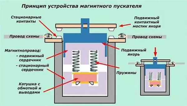
Magnetic starter device
In the absence of nutrition, the spring is pressed the upper part of the magnetic circuit, contacts are in the initial state. When the voltage appears (the start button, for example), the coil generates an electromagnetic field that attracts the upper part of the core. At the same time, the contacts change their position (on the photo the picture on the right).
When the voltage disappears, the electromagnetic field also disappears, the springs are pressed the movable part of the magnetic pipeline up, the contacts are returned to its original state. This is the principle of operation of the eclectromagnetic starter: when the voltage is applied, the contacts are closed, when disappeared - open. To feed on the contacts and connect to them any voltage - at least constant, at least variable. It is important that its parameters have not been more declared by the manufacturer.
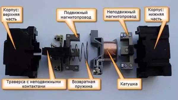
It looks like a disassembled form
There is one more nuance: a starter contacts can be of two types: normally closed and normally open. From the titles follow their principle of work. Normally closed contacts when triggered are disconnected, normally open - closed. For power supply, the second type is used, it is most common.
Magnetic starter connection schemes with 220 V
Before moving to the schemes, we will deal with what and how these devices can be connected. Most often, two buttons are required - "Start" and "Stop". They can be performed in separate housings, and may be a single case. This is the so-called push button post.
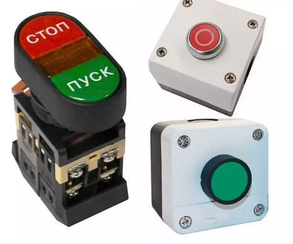
Buttons can be in one case or in different
With separate buttons, everything is clear - they have two contacts. One is supplied to me, from the second it goes away. In the post there are two groups of contacts - two for each button: two on the start, two on the stop, each group for its part. Also, there is usually a terminal for connecting grounding. Also nothing complicated.
Connecting a starter with a coil 220 to network
Actually, the options for connecting contactors a lot, we describe several. The diagram of connecting the magnetic starter to a single-phase network is simpler, because we will start with it - it will be easier to figure it out further.
Power, in this case, 220 V, it is believing the conclusions of the coils, which are denoted by A1 and A2. Both of these contacts are located at the top of the case (see photo).
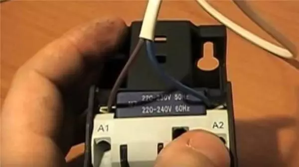
Here you can feed food for the coil
If these contacts connect the cord with a fork (as in the photo), the device will be in operation after the plug insert into the socket. To the power contacts L1, L2, L3, you can apply any voltage at the same time, and it will be possible to remove it when the starter is triggered from the contacts T1, T2 and T3, respectively. For example, a constant voltage from the battery can be served on the inputs L1 and L2, which will feed some device that will be connected to the outputs T1 and T2.
Article on the topic: Why should it be grounded by a bath?
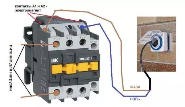
Connecting contactor with a coil at 220 V
When connecting one-phase power supply to the coil, it does not matter to which conclusion is zero, and on which phase. You can cross the wires. Even most often a phase is served on A2, as for convenience, this contact is revealed on the underside of the case. And in some cases it is more convenient to use it, and "zero" connect to A1.
But, as you understand, such a diagram of connecting a magnetic starter is not particularly convenient - you can also file directly from the power source by binding the usual switch. But there are much more interesting options. For example, it is possible to supply the power to the coil through the time relay or the illumination sensor, and to the contacts connect the outdoor lighting line. In this case, the phase is turned on the contact L1, and the zero can be taken by connecting to the corresponding coil outlet connector (in the photo above it is A2).
Scheme with "Start" and "Stop" buttons
Magnetic starters are most often set to turn on the electric motor. It is more convenient to work in this mode with the "Start" and "Stop" buttons. They are consistently included in the phase supply chain to the output of the magnetic coil. In this case, the scheme looks like in the figure below. note that
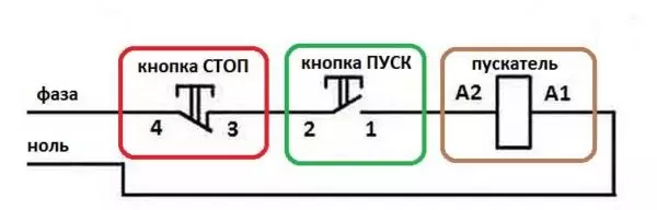
Magnetic starter switching circuit with buttons
But with this method of inclusion, the starter will be in operation only the time until the "Start" button is retained, and this is not what is required for long-term engine operation. Therefore, the so-called chain of self-grade is added to the scheme. It is implemented using auxiliary contacts on the NO 13 and NO 14 launcher, which are connected in parallel with the start button.
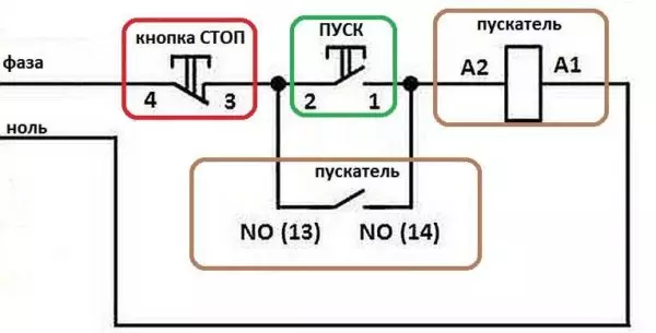
Connection diagram of the magnetic starter with a coil at 220 V and a chain of self-grade
In this case, after returning the start button to its original state, the power continues to flow through these closed contacts, since the magnet is already attracted. And the power is powered until the circuit is torn by pressing the "Stop" key or the thermal relay key, if such is in the diagram.
The power supply for the engine or any other load (phase from 220 V) is supplied to any of the contacts indicated by the letter L, and is removed from the contact with the T. marking.
It is shown in detail in which sequence is better to connect the wires in the following video. The whole difference is that not two separate buttons, but a push button post or push-button station. Instead of a voltmeter, you can connect the engine, pump, lighting, any device that works from 220 V.
Article on the topic: Wall and ceiling bamboo panels - Freshness of the forest in your room
Connecting an asynchronous engine at 380 V through a 220-to-steer starter
This scheme differs only in that it is connected to contacts L1, L2, L3 three phases and also three phases are loaded. On the reel - Contacts A1 or A2 - one of the phases will start (most often the phase with both less loaded), the second contact is connected to the zero wire. A jumper is also installed to maintain the power supply of the coil after the start button is released.
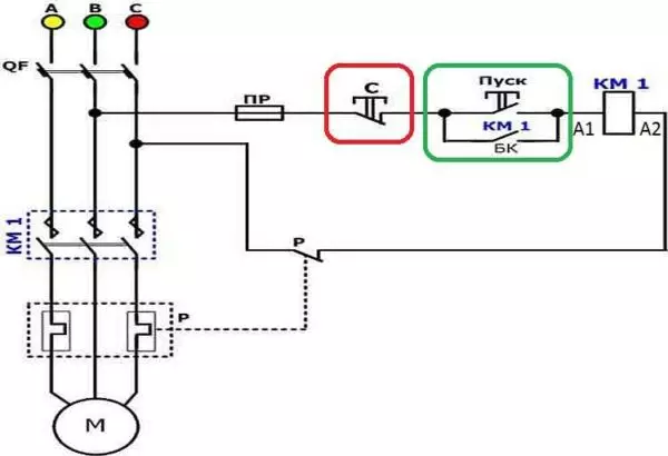
Connection diagram of a three-phase motor through a 220 trigger
As you can see, the scheme has not changed. Only it added a thermal relay that protects the engine from overheating. The order of assembly is in the following video. Only the assembly of the contact group is distinguished - all phase dials are connected.
Reversible Motor Connection Scheme Through Starters
In some cases, it is necessary to ensure the rotation of the engine in both directions. For example, to work the winch, in some other cases. The change in the direction of rotation occurs due to the transfer of phases - when connecting one of the starters, two phases should be swapped (for example, phases B and C). The scheme consists of two identical starters and a button block that includes a common stop button and two "back" and "forward" buttons.
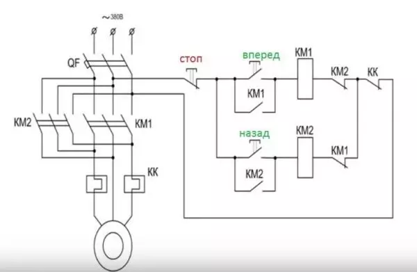
Reversible Connection Diagram of the Three Phase Motor through Magnetic Starters
To increase the safety, a thermal relay is added through which two phases pass, the third is supplied directly, since protection on two more than enough.
Starters can be with a coil at 380 V or 220 V (indicated in the characteristics on the lid). If it is 220 V, one of the phases (any) is supplied to the contacts of the coil, and "zero" from the shield is served on the second. If the coil is 380 V, two any phases are served on it.
Also note that the wire from the power button (right or left) is not applied immediately to the coil, but through constantly closed contacts of another starter. Near the coil of the starters depicted contacts KM1 and KM2. Thus, an electrical lock is implemented, which does not allow you to use two contactors at the same time.
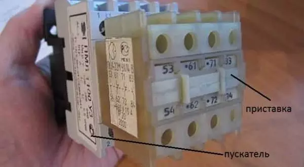
Magnetic starter with a contact console installed on it
Since normally closed contacts are not in all starters, you can take them by installing an additional block with contacts, which is also called the contact prefix. This prefix snaps into special holders, its contact groups work together with the groups of the main building.
The following video implements a diagram of connecting a magnetic starter with a reverse on an old booth using old equipment, but the overall procedure is clear.