
Engine starter

Reliable launch of a passenger car engine in winter can sometimes turn into a problem. This issue is especially relevant for the powerful autotractor equipment of agricultural enterprises, road communal services that exploit it under conditions of girlfling storage. This will not happen if the electronic assistant will be at hand, which can be made by a radio ample qualification.
The starting device of this type was manufactured according to the recommendations described in the "Starting Device" article (I.P. RESELETS. Radio Piters useful schemes. Book 1. M.: "Solon" 1998. S.95 - 96). The first tests have shown that it is possible to call it a starting device with a known proportion. It can only work in the "cigarette lighter" mode, i.e. Together with the car battery, and therefore it would be more correct to call it a charging and starting device. At low ambient temperatures, the engine start had to be carried out in two stages:
- recharging the battery for 10-20 seconds;
- Joint "promotion" of the engine.
The acceptable frequency of the starter rotation remained 3-5 seconds, and then decreased sharply. If the engine did not start from the first attempt, I had to repeat everything first. So, several times. This procedure is not only tedious, but not desirable for two reasons:
leads to overheating of the starter and its elevated wear;
Reduces the battery life (in winter, the starting currents of passenger cars reach 250 A. They cause the deformation of the battery plates, detachment of the active substance, etc.).
And the point here is not only that the rechargeable battery is "not the first freshness". As is known from the literature (N.M. Ilin, Yu.L. Timofeev, V.Ya. Vanyaev. Electrical equipment for cars. M.: Transport, 1982), the discharge capacity depends not only on battery life, but also electrolyte temperature . The rated container is guaranteed that at the electrolyte temperature + 25 ° C. With a decrease in temperature, the viscosity of the electrolyte increases, which leads to a decrease in the discharge container by about 1% per degree of temperature decrease. Thus, even a new rechargeable battery in winter significantly loses its "starting" features.
You can avoid these disadvantages only if the power of the starting device is sufficient for self (without the help of the battery) of the start of a cold car. This will also significantly extend the active battery life.
Let's try, approximately, evaluate the parameters of such a starting device. As is known from the literature [1], at the starting mode, the working current of the battery:
Ir = 3 × C20, and
where C20 is the rated capacity of the battery (and · h). Voltage at starter mode on each battery should be no less than 1.75 V. so. For a 12 volt battery:
UR = 6 × 1, 75 V = 10.5 V,
where the UR is the minimum battery operating voltage at starter mode, V.
Hence the power supplied to the starter:
PCT = UR × IP, W.
For example, if the battery is installed on a passenger car 6 ST-60, the power supplied to the start will be:
PCT = 10,5 · 3 · 60 = 1890 (W).
An exception to this rule is the battery 6 ST-55, which is the starter current of which is: IP = 255 A, and the power supplied to the starter can be:
PCT = 10.5 V · 255 A = 2677.5 W.
Using Table 1 data, you can calculate the power supplying to the starter of any car. With this power, this frequency of rotation of the crankshaft is provided (40-50 rpm - for carburetor engines and 80-120 rpm - for diesel), which guarantees reliable engine launch.
N / N. | Type of starter | Rated power, kW | Rated voltage in | Massed by engines | Rechargeable battery type | Power transformer power, kW |
one | ST 230A, ST 230B, ST230K. | 1,03. | 12 | Cars "Volga", GAZ-53, GAZ-66, ZIL-130. | 6st-60 6st-75 6st-75 6st-90. | four 4.5 4.5 five |
2. | Art 221. | 1.25. | 12 | "VAZ" | 6st-55 | four |
3. | ST 117A. | 1,18. | 12 | "Moskvich" | 6st-55 | four |
four | ST 222A. | 2,2 | 12 | Tractors T-16, T-25, T-30. | 2 × 6st-150 | 6. |
five | Art 142. | 7,73. | 24. | Cars "KAMAZ", "MAZ", "Kraz", "ZIL-133 GI" | 2 × 6st-190 | 16-20. |
6. | ST 103A-01 | 8,2 | 24. | Tractors "Kirovets", (K-700, K-701) | 2 × 6st-190 | 16-20. |
Article on the topic: Independent installation of a suspended type
Matching data Table No. 1 and calculations above, you can make several conclusions:
- For most passenger cars, the real power supplied to the starter exceeds its nominal (passportable) power by 2-2.5 times and is:
1900 ≤ PCT ≤ 2700 [W];
- For trucks with carburetor engines, this indicator may be even higher:
2400 ≤ PCT ≤ 3310 [W];
- For vehicles with a diesel engine:
PCT = 2 · 10,5 · 570 = 11970 [W],
(They have two batteries 6 st - 190 are included in series).
When calculating the lowering transformer of the starter, it is necessary to take into account the losses on the rectifier block, supplying wires, oxidized contact surfaces of the connecting adhesive and the starter conclusions. As the experience showed, the power of a lowering transformer of the starting device for a passenger car should be no less than RTR = 4 kW.
The framework was taken as described in [2], but with a more powerful transformer T1. (see Fig. 1).
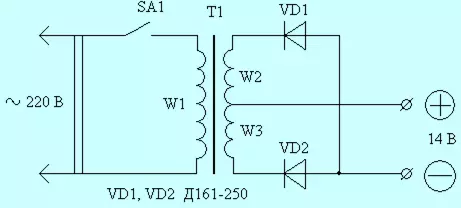
Fig.1 Scheme of a single-phase starting device.
In the author, the lowering transformer was made on a toroidal core from the stator of a burnt asynchronous electric motor with a capacity of 5 kW. Its data looks like this:
SCT = 27 cm2, SCT = A × B (SCT - the area of the magnetic pipeline cross section, cm2)
(see Fig. 2).
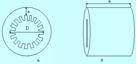
Fig. 2 A, B Magnetic Line
The number of turns of 1 in the operating voltage was calculated by the formula:
T = 30 / SS
The number of turns of the primary winding of the transformer was:
W1 = 220 · T = 220 · 30/27 = 244;
Secondary winding:
W2 = W3 = 16 · T = 16 · 30/27 = 18.
The primary winding is wound with PTTV Ø 2,12 mm, the secondary is the aluminum tire with a cross section of 36 mm2. Switch SA1 type AE - 1031 (with built-in thermal protection) for current 25 A. Diodes VD1, VD2 type D161-250.
The amplitude of magnetic induction in the core of the transformer VM = 1.7 T.. The idling current at such values of the VM reaches the values of Ixx = 3.5 A, which reduces the transformer efficiency. However, it is necessary to take into account the following circumstance. Operating current in the primary winding of the transformer i1 at the time of launch can reach the values 18-20 A, causing a voltage drop in the supply wires of the lighting network by 15-20 V. Thus, not 220 V, and 200 V. is applied to the primary winding of the transformer. Reduces the value of the VM and no idle current, which increases the transformer efficiency at the time of the start.
For those who wish to independently calculate the parameters of the downstream transformer, you can use the techniques set forth in [2], [3].
Several tips on the preparation of the toroidal core. The stator faced the electric motor free from the remnants of the winding. With the help of a sharp chisel and the hammer cut the stator's teeth. This is not difficult to do. Soft iron, but you need to use safety glasses and mittens. Then from the metal bar Ø 7-8 mm prepare two P-shaped brackets that the transformer core will be attached to the base frame. At both ends, the brackets cut the thread under the M6 nut. From a metal ribbon, a thickness of 3-4 mm and a width of 18-20 mm, bent P-figuratively, prepare a transformer handle. The edges of the P-shaped plate additionally bend towards each other, getting "tongues" of a long 5-8 cm, to which a wooden handle will be attached. To this end, the holes of Ø 7 mm are drilled in the "tongues". Two brackets and metal parts of the handle are wrapped with a layer of fabrics impregnated with epoxy resin and glued to the inside of the toroid: the handle at the top, the brackets at the bottom of the distance from each other. The entire core is also covered with one or two layers of tissue impregnated with epoxy resin. After drying the epoxy resin, begin winding the windings. The primary winding is winding first, evenly distributing around the perimeter. After performing the primary winding, the transformer includes a network and measure the idling current, which should not exceed 3.5 A. It must be remembered that at VM = 1.7 TL core close to saturation, and therefore, even a minor change in the number of turns will cause To substantial change in the current of the IXX primary winding.
Article on the topic: Is it possible to beat the fliesline wallpaper with glue for vinyl
Before winding the secondary winding in the metal part of the handle, the hole is drilled by a hole under the M12 threaded bolt, which will serve as an outlet from the middle of the winding and at the same time the "positive" terminal. The rectifying diodes shown in the diagram allows the use of metal elements of the base device framework not only for fastening diodes, but also the quality of the heat sink without dielectric pads.
The conclusions of the secondary semiotock are connected with the "positive" terminal, the turns are evenly distributed throughout the perimeter of the core. When laying use a wooden hammer.
Next, with the help of welding prepare a frame base. For this, metal rods Ø 10-12 mm are used. On one side of the frame on an aluminum or copper plate with a thickness of 3-4 mm, rectifying diodes fasten. Here the hole is drilled under the M12 bolt, which will serve as a "minus" device. On the other side of the frame, the segment of the coal is welded and the SA1 switch is attached to it.
Now about the wires connecting the starter starter. Any negligence in their manufacture can "reduce no" all your efforts. Show it on a specific example. Let the resistance of the RPR of the entire connecting path from the rectifier to the starter will be equal to: RPD = 0.01 Ohms, then at a current of the IP = 250 and the voltage drop on the wires will be:
UPR = IP · RPR = 250 A = 0.01 OM = 2.5 V;
Power loss on wires:
RPR = UPR · IP = 625 W.
As a result, a voltage is not 14 V, but 11.5 V, which, of course, is undesirable to start in the operating mode. Consequently, the length of the connecting wires should be as little as possible (L ≤ 1.5 m), and the cross-sectional area, as much as possible (SP ≥ 100 mm2). Wires must be multiple copper in rubber insulation. For convenience, the connection with the starter is made with the use of adhesive or powerful clamps used as electrode holders for household welding machines. The general type of single-phase starter is shown in Fig.3.
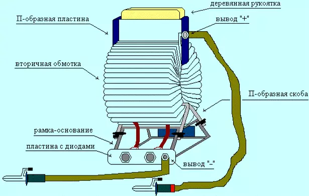
Fig.3 General view of a single-phase starting device.
The setled method of calculating the starting device is universal and applied to the engines of any power. We will demonstrate this on the example of the starter ST-222 A, used on T-16 tractors, T-25, T-30 Vladimir Tractor Plant.
Basic information about St-222 A Starter:
Rated voltage - 12 V;
Rated power - 2.2 kW;
Rechargeable battery type - 2 × 3st-150.
So:
Ire = 3 · C20 = 3 · 150 a = 450 A,
Power supplied to the starter will be:
PCT = 10.5 V · 450 A = 4725 W.
Given the loss power:
RP = 1-1.3 kW.
Power transformer power:
RTR = PCT + RP = 6 kW.
The cross section of the magnetic pipeline SCT = 46-50 cm2. Current density in windings take equal:
J = 3 - 5 A / mm2.
The short-term operation of the starting device (5-10 seconds) allows its use in single-phase networks. For more powerful starters, the starting device transformer must be three-phase. We will tell about the peculiarities of its design on the example of a starting device for a powerful diesel tractor "Kirovets" (K-700, K-701). Its starter ST-103A-01 has a rated power of 8.2 kW at a rated voltage of 24 V. The power of the starting device transformer (taking into account the loss) will be:
Article on the topic: Decorative curtains from bamboo do it yourself
RTR = 16 - 20 kW.
Simplified calculation of the three-phase transformer is carried out taking into account the recommendations set out in [3]. If possible, you can use industrial reduced TRK-20A, TMOB-63 type transformers, etc., connected to a three-phase voltage of 380/220 V and secondary voltage of 36 V. Such transformers are used for electrical heating of floors, indoors in animal husbandry, pig breeding and T .. The trigger circuit on a three-phase transformer is as follows (see Figure 4).
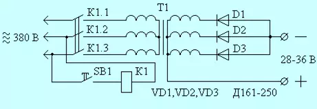
Fig.4 Starting device on a three-phase transformer.
MP is a Magnetic PML-4000 type starter, PMA-4000, or those similar to them for switching devices with a capacity of 20 kW. Pad button SV1 type KU-121-1, ku-122-1m, etc.
A three-phase single-alpapid rectifier is applied here, which allows you to obtain the idle stroke voltage of 36 V. Its increased value is explained by the use of longer cables connecting the starter starter (for large-sized equipment the cable length reaches 4 m). The use of a three-phase transformer gives more opportunities to obtain the desired stress voltage. Its value can be changed, including the "star", "triangle" winding, apply a single-alterogeneous or bippetier (Larionov circuit) straightening.
In conclusion, several general councils and recommendations:
- The use of toroidal transformers for single-phase start-up sets is not necessarily and dictated by their best mass-dimensional indicators. At the same time, the technology of their manufacturing is the most laborious.
- The calculation of the transformer of the starting device has some features. For example, the calculation of the amount of turns to 1 in the operating voltage by the formula: T = 30 / Sst, is explained by the desire to "squeeze" the maximum possible to the detriment of economy. This is justified by his short-term (5-10 seconds) mode of operation. If the dimensions do not play a decisive role, you can use a more sparing mode by calculating the formula: T = 35 / SS. The cross section of the magnetic pipeline is taken by 25-30% more.
- Power that can be "removed" from the existing toroidal core, approximately equal to the power of a three-phase asynchronous electric motor, from which this core is made. If the engine power is not known, it can be approximately calculated by the formula:
RDV = Sust × ·
where RDV is the power of the engine, W; Ѕst - the area of the magnetic pipeline cross section, cm2 set = a × in ѕok - the area of the window of the magnetic pipeline, cm2 (see Fig. 2)
Ѕok = 0,785 · d2
- The core of the transformer to the base frame is fastened with two P-shaped brackets. With the help of an insulating SHAIB, it is necessary to avoid the appearance of a co-roth-closed coil formed by a bracket with a frame.
- Considering that the idling voltage in a three-phase start-up device above 28 V, the engine starts is performed in the following sequence:
1. Connect the starting device ticks with starter outputs.
2. The driver includes a starter.
3. The assistant presses the start button of the OV1 and after the stable operation of the engine immediately releases it.
- When using a powerful starting device in a stationary version according to the requirements of the TB, it must be grounded. The handles of the connecting ticks should be in rubber insulation. In order to avoid confusion, the "positive" tick is desirable to marry, for example, a red tape.
- When starting the battery, you can not disconnect from the starter. In this case, the ticks are attached to the appropriate battery conclusions. To avoid recharging the battery, the starting device after starting the engine is disconnected.
- To reduce magnetic scattering, the secondary winding of the transformer is better to wind the first on the core, and then wound the primary winding.
Literature:
N.M. Ilyin, Yu.L. Timofeev, V.Ya. Vanyaev. Electrical equipment for cars. M.: Transport, 1982
I.P. Shelests. Radio amateur useful schemes. Book 1, M.: Solon 1998.
I. Nicoforov. Simplified calculation of the network transformer. Radio, 2000, No. 10, p. 39.
Tractors "Kirovets", K-701, K-700 A. Technical description and instruction manual. M.: Tractoroexport.
V. Motuzas. Electropuscat. Rural mechanic, 1988, No. 4, p. 23-24.